How 3D technology works
Various 3D media all work by giving the illusion of depth by
presenting offset images separately to each eye. The human brain then combines
these images to form a 3D image. Techniques for achieving this include glasses
to combine two images, glasses which filter offset images from a single source
or to have the light source split so that each eye sees a different offset
image.
Separate Images:
This technique used two different images, each shown to one eye to achieve stereoscopy. This technique was invented y Sir Charles Wheatstone in 1838. This has been used in early 3D picture cards, penny arcade machines, Viewmaster toys and world war two surveillance pictures. The viewers used are normally designed for one person to view the image at a time.
Using positive curvature (magnifying) lenses, the focus point of the image is changed from its short distance (about 30 to 40 cm) to a virtual distance at infinity. This allows the focus of the eyes to be consistent with the parallel lines of sight, greatly reducing eye strain. The card image is magnified, offering a wider field of view and the ability to examine the detail of the photograph. The viewer provides a partition between the images, avoiding a potential distraction to the user.
Disadvantages of stereo cards, slides or any other hard copy or print are that generally only one person at a time can view the media and the two images are likely to receive differing wear, scratches and other decay. These result in stereo artefacts when the images are viewed which compete in the mind resulting in a distraction from the 3D effect, eye strain and headaches. Because of these disadvantages, this system is not widely used.
Figure 1 shows some examples of side-by-side viewers and figure 2 is an example of a side-by-side picture.
|
 |
 |
 |
 |
Figure 1: Side-by-side viewers

Figure 2: Exmple of a side-by-side picture.
Filtered Offset Images:
This technique relies on the separation of two images superimposed on top of each other. This is done using colour (anaglyphs and Dolby 3D), polarized light (RealD and Imax 3D) or by using synchronized shutters (Active 3D).
Anaglyphs:
This technique uses colour layers which are filtered using coloured glasses. Anaglyph images are made up of an image in one colour for one eye overlaid with an offset image in another colour for the other eye. For example to produce a red/blue picture, two cameras shoot a scene simultaneously. They can either have a red filter, and a cyan filter, or the green and blue can be removed from the left picture and the red from the right picture. The two pictures are then superimposed to produce the anaglyph image. When viewed through red-

Figure 3: A red/cyan anaglyph picture, taken outside my spare room in Carterton, UK.
This technique was first developed in 1853 by Wilhelm Rollmann in Leipzig who used red and blue lines on a black background to produce 3D images viewable using red and blue glasses. In 1858 Joseph D’Almeida produced an anaglyph magic lantern show using red and green filters and the audience wearing red and green goggles. The first printed anaglyphs were produced in 1891 by Louis Ducas Hauron by printing two negatives on the same paper, on in red and one in either green or blue. The first anaglyph film was presented on June 10th, 1915 by Edwin S. Porter and William E. Waddell in the Astor Theatre in New York using red-
A second wave of anaglyph movies occurred in the early 1980s with such films as Jaws 3D, , Amityville 3D and Friday 13th Part III. Anaglyphs also have the advantage that they can be shown on any colour TV and in the 1980s some 3D films were shown as anaglyphs. Since then, polaroid systems have largely taken over the 3D format in cinemas and traditional anaglyph pictures and movies can be found in places such as children’s comics and books, molecular modelling software and on the internet. An exception to this is the Dolby 3D and Infitec systems. These use red, green and blue light of different frequencies for each eye. This makes it possible to have full colour images shown to each eye and the quality is comparable to the polaroid systems in terms of picture quality.
The colours schemes used are given below. Most use one of the six possible combinations of colours possible for pure anaglyphs: red-
A more advanced form of anaglyphs is wavelength multiplex visualisation, also known as super-
| Scheme | Left eye | L | R | Right eye | Colour Rendering | Description |
|
red- |
pure red | pure green | monochrome |
The predecessor of red- |
||
|
red- |
pure red | pure blue | monochrome | No ghosting on screens as there is no overlap between the colours the filters let through. Often used for printed materials. | ||
|
red- |
pure red | pure cyan (green+blue) | colour (poor reds, good greens) |
Patent- |
||
| anachrome | dark red | cyan (green+blue+ some red) | colour (poor reds) |
A variant of red- |
||
| mirachrome | dark red+lens |
|
cyan (green+blue+ some red) | colour (poor reds) | Same as anachrome, with addition of a weak positive correction lens on the red channel to compensate for the chromatic aberration of eyes. | |
| Trioscopic | pure green | pure magenta (red+blue) | colour (better reds, oranges and wider range of blues than red/cyan) |
Same principle as red- |
||
| INFICOLOUR | complex magenta | complex green | colour (almost full and pleasant natural colours with excellent skin tones perception) | Developed by the TriOviz company, INFICOLOUR 3D is a newer, patent pending stereoscopic system first demonstrated at International Broadcast Convention in 2007 and deployed in 2010. It works with traditional 2D screens and TV sets (LCD, Plasma) and uses glasses with brand new complex colour filters and dedicated image processing that allows a natural colour perception with a pleasant 3D experience. When observed without glasses only some slight doubling can be noticed in the background of the action which allows watching the movie in 2D without the glasses. This is not possible with traditional brute force anaglyphic systems. | ||
| ColourCode 3D | amber (red + green + neutral grey | pure dark blue (+optional lens) |
colour (almost full- |
Also named yellow- |
||
|
magenta- |
magenta (red+blue) | cyan (green+blue) |
colour (better than red- |
Experimental; similar to red- |
||
| Infitec | white (Red 629 nm, Green 532 nm, Blue 446 nm) | white (Red 615 nm, Green 518 nm, Blue 432 nm) | colour (full colour) |
Uses narrow- |
Polaroid Systems:
Polaroid systems work by exploiting the polarisation of light to achieve the 3D effect. This is achieved by projecting two images superimposed over each other, each image having a different polarisation. The Viewers wear glasses which contain polarised filter which blocks the unwanted image from each eye. Two types of polarised system exist, linear and circular. The main advantage of polarisation system is that full colour is retained for both eyes.
Linear polarised systems
This is the original system, developed in 1936 by Edwin H. Land. This technique was used in the first 3D boom in the early 1950’s and is still used in Imax cinemas. Two images are projected superimposed onto the screen through orthogonal polarising filters, usually at 0º and 90º, shown in figure 4. The glasses worn by the viewers also contain a pair of orthogonal polarising filters oriented the same as the projected images. Since each filter only allows light similarly polarised through, each eye only sees one of the two superimposed images. The main disadvantage of this technique is that the viewer must keep their head still otherwise the unwanted image will bleed into the other image causing ghosting. This can make prolonged viewing uncomfortable.

Figure 4: Linear polarised light
Circular Polarised Systems
This method uses clockwise and anticlockwise circular polarised light to achieve the same effect as linear polarisation. It has the advantage that tilting the viewer’s head does not cause the images to bleed into each other.
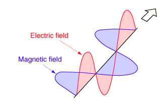
Light consists of two perpendicular waves, one magnetic and the other electric as illustrated in figure 5.

Figure 5: Electromagnetic waves
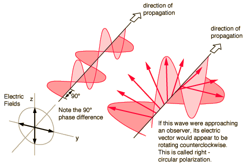
Circularly polarized light consists of two perpendicular electromagnetic plane waves of equal amplitude and 90° difference in phase. The light illustrated is right-

Figure 6: Anticlockwise circular polarised light
If light is composed of two plane waves of equal amplitude but differing in phase by 90°, then the light is said to be circularly polarized. If you could see the tip of the electric field vector, it would appear to be moving in a circle as it approached you. If while looking at the source, the electric vector of the light coming toward you appears to be rotating anticlockwise, the light is said to be right-
Circularly polarized light may be produced by passing linearly polarized light through a quarter-
The RealD system use clockwise for the right eye and anticlockwise for the left and, in the UK, is the most common type of 3D projection. The glasses have opposite polarised lenses so that each eye sees only its designated image, even if the head is tilted. The images are projected onto a silver screen which preservers the polarisation.
Active 3D Displays
This technique uses a shutter system which is synchronised with the display so that each eye sees a different image and is mainly used in 3D televisions. Liquid crystal shutter glasses most commonly used in these displays was invented in the mid 1970’s. The prototype had the LCDs mounted to a small cardboard box using duct tape. The glasses were never commercialized due to ghosting, but E&S was a very early adopter of third-
Autostereoscopy
Autostereoscopy is any method of displaying 3D images without the need for 3D glasses or other viewers. Because glasses are not needed, it is also called “glasses-
Parrallax Barrier
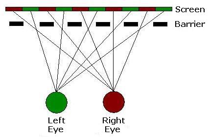
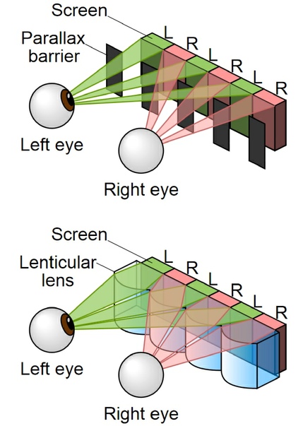
A parallax barrier consists of a barrier which has a series of slits cut out is placed in front of the display, LCD being the most common displayed used. At one of the correct viewing angles the holes allows the light from one image to be seen by one eye and the light from the other image is seen by the other eye. The barriers block the light from each of the images from being seen by the other eye. This is illustrated below.

This method is used in a navigation system installed in the 2010-
Lenticular Lens
A lenticular lens is an array of magnifying lenses, designed so that when viewed from slightly different angles, different images are magnified. The most common example is the lenses used in lenticular printing, where the technology is used to give an illusion of depth, or to make images that appear to change or move as the image is viewed from different angles. This is mainly used for printed images, but is also used for projected TV systems and glass-
Lenticular printing is a multi-
Transforming prints
Here two or more very different pictures are used, and the lenses are designed to require a relatively large change in angle of view to switch from one image to another. This allows viewers to easily see the original images, since small movements cause no change. Larger movement of the viewer or the print causes the image to flip from one image to another. (The "flip effect".)
Animated prints
Here the distance between different angles of view is "medium", so that while both eyes usually see the same picture, moving a little bit switches to the next picture in the series. Usually many sequential images would be used, with only small differences between each image and the next. This can be used to create an image that moves ("motion effect"), or can create a "zoom" or "morph" effect, in which part of the image expands in size or changes shape as the angle of view changes. The movie poster of the film Species II, shown in this article, is an example of this technique.
Stereoscopic effects
Here the change in viewing angle needed to change images is small, so that each eye sees a slightly different view. This creates a 3D effect without requiring special glasses.
Lenticular lenses are used to produce a bright picture on projected TV screens. It is not used in this way for 3D projected television. It is used in some glasses-

Summary Table
Comparison between Parallax Barrier and Lenticular lenses
|
Technique |
Advantages |
Disadvantages |
Uses
|
|
Side- |
Full colour image
Full brightness
Reduced Eyestrain
|
Only one person can see image at a time
Differing wear can distort 3D
|
Stereographic postcards
Aerial photo reconnaissance
|
|
Anaglyphs |
Cheap
Simple
Lightweight glasses
|
Colours appears distorted |
Comics and children’s books
3D films on the internet
|
|
Wavelength Multiplex Visualisation |
Full colour
Brighter than other 3D systems
Expensive silver screens not needed
|
Glasses more expensive and fragile than polarisation techniques |
3D cinemas (Dolby 3D and Infitec Dualcolor3D) |
|
Linear Polarisation |
Cheap glasses
Lightweight glasses
Full colour images
|
Ghosting can occur if views head is tilted
Reduced image brightness
|
3D cinemas (Imax 3D) |
|
Circular Polarisation |
Cheap glasses
Lightweight glasses
Full colour images
Reduced resolution (for TVs)
|
Incorrect parallax can occur if head is tilted
Reduced image brightness
|
3D cinemas (RealD and MasterImage 3D)
Passive 3DTV (LG’s 47LD950 3DTV)
|
|
Active 3D |
Full high definition image (for 3DTV)
Lower cost 3DTVs
|
Expensive glasses
Heavy glasses
Complicated glasses
Reduced refresh rate (for 3DTV)
Image can seem to flicker by some people
|
3DTV
Cinemas (XpanD 3D)
|
|
Autostereoscopy |
Glasses free |
Limited viewing angle
Multiple views can be jarring when moving from one view to the next
|
3D posters
Heldheld 3D displays (Nintendo 3DS)
|
Further Reading
Wikipedia pages:

